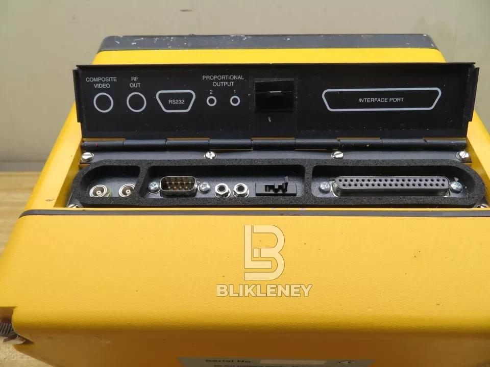
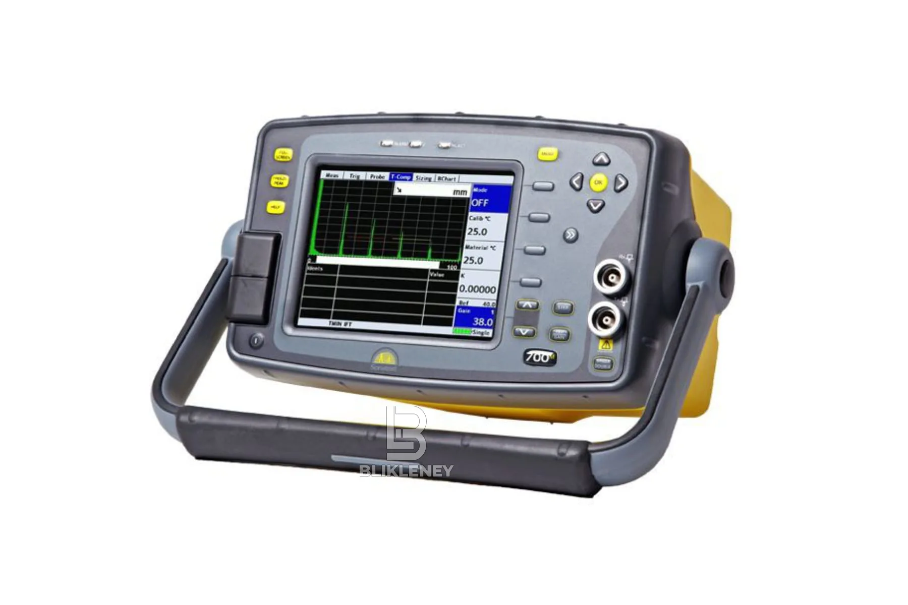
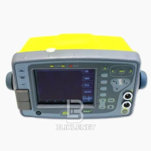
Sonatest Masterscan 700M Flaw Detector offers the end user a high end narrowband flaw detector with a full VGA display, sync and proportional outputs, sync input and a Spike and Square Pulser.
Sonatest Masterscan 700M Flaw Detector can be added and upgrades performed in the working environment, reducing downtime and increasing working flexibility. Sonatest Masterscan 700M Flaw Detector high levels of near surface resolution, penetrating power (450V pulser – square and spike) and Sonatest Masterscan 700M Flaw Detector excellent signal to noise ratio are key functions in the Masterscan range.
Sonatest Masterscan 700M Flaw Detector typical applications are Weld Fabrication, Corrosion Detection, Composite Inspection, Bond Testing, Forgings & Castings, Power Generation (including EMATS) and general UT inspection.
Sonatest Masterscan 700M Flaw Detector Features:
- Reliable, Rugged & Robust
- Advanced Defect Sizing Tools as Standard
- UT-Lity Data Management Software
Sonatest Masterscan 700M Flaw Detector Included:
- DAC (Standard)
- Split DAC & DGS / AVG (Option)
- TCG (Option)
- Backwall Echo Attenuation (BEA) Option (requires TCG)
- AWS (Option)
- AVG / DGS Option
- API (Option)
- Interface Trigger (Option)
- Corrosion Software (Option)
- Dryscan Function (Option)
- Load, store, manage files both on the PC and on a connected flaw detector
- Save, analyse, colour code and export thickness logging data to spreadsheets/asset management software
- Update the Flaw Detector and Firmware as and when updates become available on our website
You may also be interested in Sonatest Railscan 125 Plus Flaw Detector
Sonatest Masterscan 700M Flaw Detector Specifications:
| Test Range | 0-1mm (0.04in) up to 0-20,000mm (787in.) in steel at 5930m/s (19455f/s) |
| Velocity | 256 – 16000m/s continuously variable |
| Probe | Zero 0 to 1000μs |
| Delay | 0-20,000m (800in) in steel at 5930m/s |
| Gain | 0 to 110dB adjustable in 0.1, 0.5, 1, 2, 6, 14 and 20dB steps |
| Test Modes | Pulse echo and transmit/receive. Single Crystal, Double Crystal and Pitch-Catch |
| Damping | 50 and 400Ohm damping selectable |
| Pulser | 100-450V -ve spike and square wave. Pulse Width from 30nS to 2500nS. Rise/Fall times <5nS into 50R load |
| P.R.F. | Adjustable 5Hz to 6kHz. External sync also available |
| Screen Update Rate | 60Hz |
| Rectification | RF, Full wave, +ve half-wave and -ve half-wave |
| Frequency Range | 8 selectable filter bands. i) 100kHz – 500kHz ii) 200kHz – 800kHz iii) 0.4MHz – 1.6MHz iv) 1.4MHz – 3MHz v) 3MHz – 8MHz vi) 7MHz – 15MHz vii) 9MHz – 21MHz viii) 1.6 MHz – 33 MHz (Wideband) Additional tuned low frequency pre-amp with Dryscan option |
| System Linearity | Vertical = 0.5% Full Screen Height (FSH). Horizontal +-0.2% Trace Full Screen Width (FSW) |
| Reject (Selectable) | Up to 80% Linear reject (removes baseline noise without affecting indication amplitude) Or Up to 50% Suppressive reject (increase zero offset and reduces amplitude of all echoes) LED Warning when active. |
| Units | Metric (mm), inch (in) or microseconds |
| Display | Colour Transflective VGA (640 x 480) TFT. Display area: 116.16 x 87.2mm (4.57 x 3.43in). A-Scan Area: 400 x 510pixels (normal), 460 x 620 (FS). Colours: 9 colour options with variable brightness. |
| Gate Monitor | Two independent gates for measurement and monitoring. Start and width fully adjustable over the entire range of the instrument. Levels adjustable from 0% to 100%, positive or negative triggering on each gate with audible & visual alarms. Gate resolution is 5nS. |
| Zoom | Expands range and delay to cover the area set by Gate 1 start & width controls. |
| AGC | Automatic Gain Control automatically sets the signal in Gate 1 to a level between 10% and 90% FSH, tolerance between 5% and 20%. |
| Measurement Nodes | |
| Mode 1 | Signal monitor, Gate alarms can be active but no measurements are displayed |
| Mode 2 | Depth and amplitude of first signal in gate |
| Mode 3 | Echo-Echo distance measurements |
| Mode 4 | Trigonometric display of beam-path, surface distance (including X-offset) and depth of indication from the inspection surface together with echo amplitude. Curved surface correction can be applied for convex and concave surfaces. Half-skip can be indicated on screen. |
| Mode 5 | Gate to Gate distance measurement |
| Mode 6 | Flank to Flank |
| Mode 7 | Beam Angle, calculated from beampath, hole radius and hole centre depth. |












Reviews
There are no reviews yet.